Page 34 of 38
Re: Project Delilia
Posted: Thu Jul 09, 2009 4:20 pm
by TheGoodGuy
SF5 wrote:hmmm, you underestimate the importance of shielding. it reduces noise and interferance in signals. the cam and crank are reluctors similar to tiny electro magnets, the crankk sprocket has a wheel i think its 36-1 or 12 to 1 memory not too sharp. now the 36 represents the number of teeth, every time the wheel spins a variation in the magnetic field is formed, creating a wavelike signal whick can be seen with an oscilloscope... this tells the ecu when to fire coil and injectors. this knowledge wasnt grasped from a website, thats from making ems and messing with standalones ecu. so if your shields arent right jump high or low you wont ever run right. and more possibly than not your issue is ca,/crank signal related.. case close.
Will look for that ground.. if its not there or has no sign of ever being there.. should I assume that its not grounded? I noticed the crank sensor has a ground wire round the pair of wires raping around them.. it grounds to the bolt that holds it on the block. Appears to be factory.. I am guessing thats one of the shields.
I might end up grounding the shit out of that car.. lol.. time will tell... once I feel in the mood I will do it. Right now.. I a bit fed up and just want to put it on the road. But still taking note of post like this for when I go behind it again.
Re: Project Delilia
Posted: Sat Jul 11, 2009 11:19 pm
by TheGoodGuy
The ground is intact... saw it.
Re: Project Delilia
Posted: Sun Jul 12, 2009 6:45 pm
by SF5
you have noise problem skipper get an oscilloscope and check that. if u can't get an osscilloscope get a timining light. lock the timing and then see if it stays constant if it doesn't then u have interferance.
Re: Project Delilia
Posted: Wed Jul 15, 2009 1:19 pm
by TheGoodGuy
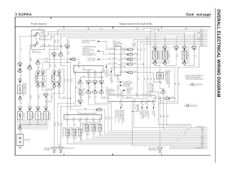
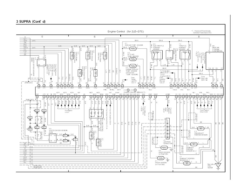
Dell on the wiring diagrams pages 247 and 246 look at EFI no2. Relay.. then trace the wire colour B-R. I suspect this wire I am not sending power to it.. which would explain why my IAC valve and the VSV for the turbo's not working.
The EFI Main relay is wired as the diagram with the M-Rel initiating the coil but it only goes to +B on E10. When I map out wire B-R I see it supplying positive power to the VSV valves ... IAC and Oxygen sensor.. My theory is this.. I suspect that the reason that the VSV, IAC isn't working and even possibly the Oxygen sensor.. (possible rev issue).. is because its not getting a +12V power.
These Items also need to be connected to the EFI Main Relay... Ontop of this.. I went through the pinout of the E9 and E10 plugs and I cant see a positive feed to the VSV, IAC, Oxygen sensor..and who knows what else. Seems the ECU manipulates the negative connections and the positive connection may be a constant +12V like the coils. Either way I gonna test this theory out with a multimeter.
Check the diagrams and let me know what you think.
Edit.. Got the images off the PDF.. May have to save the image then zoom in on it.
Page 246
Page 247
Re: Project Delilia
Posted: Wed Jul 15, 2009 9:43 pm
by SF5
See when I asked you if the IAC getting voltage you said yes. I asked u if it is making a tuck tuck tuck sound when the car is just turned off. Anyway if you're not getting voltage to those things why don't u test ur theory, send voltage to them but beware if u put voltage to the wrong thing u will blow the ecu.
Re: Project Delilia
Posted: Wed Jul 15, 2009 9:48 pm
by TheGoodGuy
SF5 wrote:See when I asked you if the IAC getting voltage you said yes. I asked u if it is making a tuck tuck tuck sound when the car is just turned off. Anyway if you're not getting voltage to those things why don't u test ur theory, send voltage to them but beware if u put voltage to the wrong thing u will blow the ecu.
I will test the B-R wire across the VSV valves and IAC for continuity... if they are all linked I should get some continuity.. then I send some power to it and start the engine.. see if my turbos.. or better yet.. see if the idle changes.
Think it could possibly be the prob with the rev.. no O2 sensor signal.. hmm dumping tomuch fuel.. or what?
No tuck tuck tuck.. sound.. minimal to no voltage when tested. But I didn't know what I was doing..exactly.. But now I have a good idea of what wires I am looking for.
Re: Project Delilia
Posted: Wed Jul 15, 2009 10:00 pm
by SF5
before u do this here's a simple test,
the ecu has a diagnostic test code which is set by jumping te1 to e1 that will give the code for any malfunctions then turning on the ignition, check light will flash. thats basic code reading
Now there is test mode, which actually allows u to run the engine under normal conditions and will blink for any malfunctions that occur regardless of whether mil is on. it will tell u whats not functioning right. Then hit me back to do this jump te2 to e1. Start car then rev it or drive if possible. All codes will flash I don't know how u gonna get the codes if its a trans code. do that
Re: Project Delilia
Posted: Wed Jul 15, 2009 10:05 pm
by SF5
the iac has six wires, 2 power and 4 ground
the grounds aren't continuous they move along in a sequence pushing or pulling the arm inside and out
Re: Project Delilia
Posted: Wed Jul 15, 2009 10:26 pm
by TheGoodGuy
SF5 wrote:Now there is test mode, which actually allows u to run the engine under normal conditions and will blink for any malfunctions that occur regardless of whether mil is on. it will tell u whats not functioning right. Then hit me back to do this jump te2 to e1. Start car then rev it or drive if possible. All codes will flash I don't know how u gonna get the codes if its a trans code. do that
Was going through these steps once.. but number 9 had me baffled. Page 6 troubleshooting 2jz-gte. Do you keep TE2 and E1 connected after simulating the conditions and in addition connect TE1 to E1... so in total have two "SST's" both leaving E1 going to TE1 and TE2.. I would assume from number 9 directions..
I guess after its off... you use TE1 to present the codes from the test mode?.. I not going to test these things out..soon.. well this week. I wanna put her on the road. But when she outside my house.. after work.. You will bet ery other day of the week I will be under that bonnet testing theories.. till It gets resolved.
Re: Project Delilia
Posted: Thu Jul 16, 2009 4:34 pm
by SF5
with car off to enter test mode which will run through and check every circuit and sensor from fuel pump to starter signal. jump te2 to e1. then turn key on, then start car. then drive car then read codes as they flash. this will give you all your issues. you may have about 5 or 6 of them. dont read while driving tho.